How to Identify Parts of Injection Moulding Machine?

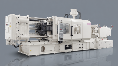
Identifying the parts of injection moulding machine is essential for safe operation, accurate troubleshooting, and consistent product quality. A moulding machine may look like one large steel system, but each section performs a specific task. The injection unit melts and pushes plastic, while the clamping unit closes the mould with controlled force. Hydraulic or electric systems provide movement, pressure, and timing.

John Bozzelli, a respected injection moulding consultant and educator, often states, “If you cannot measure it, you cannot control it.” This principle applies directly to machine identification. Operators should inspect the hopper, barrel, screw, nozzle, mould platens, tie bars, ejector system, and control panel. Small details matter. A worn nozzle can create leakage. A damaged tie bar can threaten mould alignment. A blocked cooling channel can leave visible defects on the product.

Experience also teaches caution. Machine layouts vary between manufacturers, and similar components may use different names. This can confuse new technicians. A screw, for example, is not simply a rotating rod; its zones control melting, mixing, and pressure development. Technical manuals remain necessary, even for experienced operators. I have found that photographs, labels, and maintenance records improve identification accuracy. Still, no checklist replaces careful observation. Look closely. Listen for unusual sounds. Check temperature, pressure, and movement before making adjustments. Understanding the parts of injection moulding machine creates a stronger foundation for maintenance, fault diagnosis, and safer production. Mistakes can happen, especially when older machines lack clear markings. That limitation deserves honest attention.
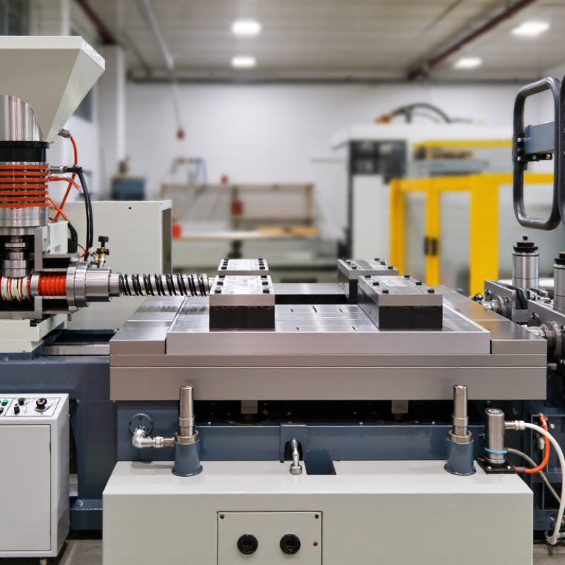
How to Identify Parts of Injection Moulding Machine?

Identify the Main Systems: Injection, Clamping, Hydraulic, and Control Units

Identifying an injection moulding machine becomes easier when you trace its four main systems: injection, clamping, hydraulic, and control. Start with the injection unit, usually positioned along the machine’s centerline. Look for the hopper, heated barrel, screw drive, and nozzle. The hopper holds plastic pellets, while the rotating screw conveys and melts them. Pressure leaves clues. A pressure gauge, screw position sensor, or injection carriage can confirm this system’s location. In practice, labels may be missing, so physical inspection matters more than diagrams alone.

The clamping unit sits around the mould area. It includes the fixed platen, moving platen, tie bars, and toggle or direct clamping mechanism. Watch the mould area. The moving platen opens and closes the mould, while the tie bars keep movement aligned. Check for uneven wear, oil marks, or unusual movement. These details can reveal maintenance issues, although visual evidence is not always conclusive.

The hydraulic system powers movement and pressure in many machines. Identify the pump, motor, valves, hoses, reservoir, and pressure filters. Follow the hoses carefully; their routing often explains each function.

The control unit contains the operator panel, electrical cabinet, sensors, and safety interlocks. It manages temperature, speed, pressure, and cycle timing. A displayed value is useful, but it should not be trusted blindly. Compare readings with gauges and machine behaviour. Always isolate energy sources before opening guarded areas or inspecting internal components.

Map the Clamping Unit: Platens, Tie Bars, Mold Height, and Force in kN

When identifying an injection moulding machine, begin with the clamping unit. It holds the mould closed during injection and cooling. The fixed platen supports the stationary mould half. The moving platen carries the opposite half and travels along the tie bars. Check the platen faces for locating rings, mounting slots, ejector openings, and nozzle clearance. These details reveal how the mould is installed. Wipe away grease first. Small marks can hide damage.

Four tie bars usually guide the moving platen and transmit clamping force. Inspect their surfaces for scoring, rust, or uneven lubrication. A damaged tie bar may affect platen alignment and mould life. Do not assume every machine uses identical spacing. Measure the distance between bars, both horizontally and vertically. Record the values carefully.

Mold height, also called shut height, means the closed thickness of the mould between the platen faces. Compare this measurement with the machine’s stated minimum and maximum range. Include the complete mould stack, such as plates and spacers. Do not confuse mold height with opening stroke. Clamping force is commonly shown in kilonewtons, or kN. It keeps the mould closed against cavity pressure and helps prevent flash. Read the machine plate or control display, rather than guessing from motor size. A larger number is not automatically better. I once focused only on force and missed the mould-height limit. That mistake delayed setup and required another measurement. Check alignment, dimensions, and force together.

How to Identify Parts of Injection Moulding Machine? - Map the Clamping Unit: Platens, Tie Bars, Mold Height, and Force in kN
Reference map for identifying the main clamping-unit components. Listed ranges are representative values for general industrial injection moulding machines; the actual specification depends on machine design, mould dimensions, material, and application.
Clamping-Unit Part What to Identify Representative Data or Range Unit / Relationship Purpose and Inspection Point
Fixed Platen The stationary front plate where the mould’s fixed half and injection nozzle interface are mounted. Platen width and height: approximately 400–2,000 mm on general industrial machines. Dimensions are normally specified as width × height in mm. Check the mounting face for flatness, damage, corrosion, and correct locating-ring or nozzle alignment.
Moving Platen The rear plate that travels along the tie bars and carries the moving half of the mould. Travel: commonly about 200–1,500 mm, depending on machine size and mould height. Opening travel must provide enough clearance for mould removal and part ejection. Inspect platen movement, guide condition, parallelism, and the security of mould-clamping bolts.
Tie Bars Four high-strength columns connecting the fixed and moving platens and transmitting the clamping load. Typical diameter: approximately 40–180 mm. Four tie bars are common on standard machines. Tie-bar spacing is measured center-to-center in mm and defines the usable mould footprint. Check for scratches, wear, cracks, lubrication problems, and uneven strain or elongation.
Tie-Bar Spacing The horizontal and vertical distance between adjacent tie-bar centerlines. Typical spacing: approximately 250–1,600 mm, depending on machine capacity. Usable mould width and height must be smaller than the clear tie-bar opening. Confirm that the mould can pass between the tie bars without interference from connectors, clamps, or hoses.
Clear Tie-Bar Opening The free rectangular space between the tie bars, measured inside the tie-bar centers or surfaces according to the machine drawing. Typical clear opening: approximately 200–1,450 mm. Clear opening = tie-bar center spacing − tie-bar diameter, when measured between opposing bar surfaces. Use the machine manufacturer’s drawing because measurement conventions may differ between specifications.
Mould Height The closed thickness of the mould between the fixed and moving clamping faces. Typical range: approximately 150–1,200 mm. Also called mould thickness or die height; it must fall between the machine’s minimum and maximum mould-height limits. Measure the complete closed mould, including mould plates that contact the platens, but exclude external hoses and fittings.
Minimum Mould Height The thinnest mould that can be installed while maintaining the required clamping and adjustment range. Typical value: approximately 150–400 mm on many general-purpose machines. A mould thinner than this limit may require an approved spacer or adjustment solution. Verify that the mould closes correctly and that the toggle or hydraulic system reaches its intended lock position.
Maximum Mould Height The thickest mould that can be accommodated with the available mould-height adjustment. Typical value: approximately 500–1,200 mm on many general-purpose machines. Maximum mould height must be compatible with the available opening stroke and ejector stroke. Confirm that the mould can open far enough to remove the part and that the mould does not exceed adjustment limits.
Opening Stroke The distance travelled by the moving platen from the mould-closed position to the mould-open position. Typical range: approximately 200–1,500 mm. Required opening stroke depends on part depth, mould design, runner system, and demoulding method. Ensure that the stroke provides sufficient daylight for part removal without over-travelling the machine.
Maximum Daylight The greatest distance between the fixed and moving platen faces when the mould is fully open. Typical range: approximately 400–2,700 mm. Maximum daylight is generally related to mould height plus opening stroke. Maximum daylight must be sufficient for mould installation, robot access, and safe part extraction.
Clamping Force The force that holds the mould halves closed during injection and packing. Typical range: approximately 500–10,000 kN for general industrial machines. 1 kN = 1,000 N; 1 tonne-force is approximately 9.81 kN. Select sufficient force to resist mould-opening pressure while avoiding unnecessary stress on the mould and machine.
Required Clamping Force The estimated force needed to keep the mould closed during filling and packing. Basic estimate: clamping force ≈ projected area × average cavity pressure. In SI units: F (N) = A (m²) × P (Pa). Convert the result to kN by dividing by 1,000. Include the projected area of the parts and runners. Add an engineering safety margin based on the process and material.
Projected Area The silhouette area of the moulded parts and runner system projected onto the mould-parting plane. Example: 0.020 m² at 50 MPa cavity pressure requires about 1,000 kN before applying a safety margin. Projected area is normally expressed in cm² or m²; 1 m² = 10,000 cm². Use the projected area on the parting plane, not the total surface area of the moulded component.
Ejector System The ejector plate, rods, and pins that push the moulded part from the moving mould half. Typical ejector stroke: approximately 50–300 mm. Actual force varies widely by mould design. Ejector stroke must be sufficient to clear the part from the core without damaging it. Check pin alignment, return confirmation, lubrication, plate movement, and interference with the mould’s ejector system.
Mould-Height Adjustment The mechanical or hydraulic adjustment that matches the clamping unit to different mould thicknesses. Adjustment range: commonly several hundred millimetres, depending on machine size. Adjustment must keep the mould within the specified minimum and maximum height limits. Confirm correct adjustment before applying full clamping force and verify that the mould closes without excessive resistance.
Platen Parallelism The degree to which the fixed and moving platen faces remain parallel during mould closing. Typical inspection target: often measured in hundredths of a millimetre, according to the machine service specification. Parallelism is checked across the platen face with a suitable precision measuring method. Poor parallelism can cause uneven mould wear, flash, parting-line damage, and non-uniform tie-bar loading.
Technical note: Clamping-force calculations are preliminary estimates. Final machine selection should also consider injection pressure, mould stiffness, material shrinkage, parting-line design, safety margin, and the machine’s certified operating limits.

Trace the Injection Unit: Hopper, Screw, Barrel, Nozzle, and Pressure up to 250 MPa

To identify an injection moulding machine, trace the material flow from the hopper to the nozzle. The hopper sits above the rear of the injection unit. It stores plastic pellets and feeds them into the barrel. Check for a slide gate, drying connection, or level sensor. A blocked throat can look like a screw problem, but the cause may be poor material flow.

Inside the heated barrel, the screw melts, mixes, and pushes the material forward. Its flights, compression section, and non-return valve affect melting consistency. Barrel heaters and thermocouples appear along its length. At the front, the nozzle forms the final passage into the mould. Look for a heater band, tip, and alignment with the mould sprue. Keep hands away from these areas. Heat remains after shutdown.

Pressure readings require careful interpretation. Injection pressure may approach 250 MPa in some machines, while hydraulic pressure can show a different value. Confirm the unit, sensor location, and machine documentation before judging performance. A pressure spike may indicate a blocked nozzle, cold material, or incorrect settings. Do not assume the screw is at fault. During inspections, I record pressure, temperature, screw position, and shot weight together. Labels can fade, and diagrams may not match older modifications. That is an easy detail to miss. A clean flow path and stable readings provide stronger evidence than one alarm alone.

Read Screw Specifications: Diameter, L/D Ratio, Compression Ratio, and Shot Size

How to Identify Parts of Injection Moulding Machine?

The screw is a key part inside the heated barrel. Its specifications help identify the machine’s processing capacity. Start with the screw diameter, usually measured in millimetres. A larger diameter can move more material per revolution, but it also affects melting time and shear. Check the machine plate, technical drawing, or maintenance record before measuring it directly.

The L/D ratio compares the screw’s flighted length with its diameter. For example, a 20:1 ratio means the flighted section is twenty times longer than the screw diameter. A longer screw may provide better melting and mixing, but excessive residence time can damage sensitive materials. The compression ratio compares feed-zone flight depth with metering-zone flight depth. Higher compression creates stronger melting pressure. It may also increase shear and temperature. Small detail, big effect.

Shot size indicates the maximum material volume or weight the injection unit can deliver. Always check the material basis, because published values may use a standard test resin. The practical shot should leave a small cushion in front of the screw. Many processors begin around 70–90% of the rated shot, then adjust through trials. I once trusted the catalogue value too quickly; the mould still filled, but the cushion became unstable. Recheck screw position, melt density, and actual part weight. A visual inspection helps, but it cannot replace measurements.

How to Identify Parts of an Injection Moulding Machine?

Reading screw specifications: diameter, L/D ratio, compression ratio, and shot size.

The chart shows representative screw specification combinations used in general-purpose thermoplastic injection moulding. Screw diameter is measured across the flighting, L/D is the screw length divided by its diameter, compression ratio compares feed-zone depth with metering-zone depth, and shot size is the approximate maximum material volume per injection. Actual values vary by screw design, resin, and machine configuration.

Distinguish Drive Technologies: Hydraulic, Servo-Hydraulic, and All-Electric Machines

Identifying an injection moulding machine starts with its drive system. Look beside the motor and pump. A hydraulic machine usually has a fixed-speed motor, hydraulic pump, oil tank, valves, and hoses. The pump may continue running during short pauses, creating heat and energy loss. The U.S. Department of Energy reports that motor-driven systems can represent more than half of industrial electricity use, although actual savings depend on machine design and operation.

A servo-hydraulic machine adds a variable-speed servo motor to the hydraulic circuit. The motor slows during cooling and accelerates during injection. Check for a servo motor, controller, pump, and hydraulic manifold. EUROMAP 60.1 recommends measuring machine energy across defined operating conditions. This matters because quoted savings can change with mould size, cycle time, material, and part weight. Servo-hydraulic systems often reduce idle energy, but the oil system remains.

An all-electric machine uses separate servo motors for injection, screw rotation, clamping, and ejection. Look for drive motors, ball screws, belts, and electrical cabinets instead of main hydraulic piping. Industry assessments commonly report energy reductions of about 30–70% versus conventional hydraulic machines. That range is not a promise. It is a warning. On a factory floor, I still verify readings with a power meter and cycle log. Labels can mislead. A machine may appear fully electric while using a small hydraulic unit for auxiliary movement. Check the injection unit, clamp drive, control cabinet, and actual power profile before identifying the technology.

Submit a quote request or book a design consultation

Plastimold Products is an end-to-end product development and manufacturing team.  We provide product design, engineering, prototyping, tooling, plastic injection molding, assembly, packaging and fulfillment.  We work with any size company from start-ups to enterprises from all around the world.

I have a product I want to manufacture

I have a product that is already designed and now needs to be manufactured. 

I need a manufacturer to optimize my product for injection molding, help choose the correct material, and manage the product production.

I have tooling that I want to transfer or modify, or I need to produce new tooling.

I need design and engineering support

I have a product concept that I want to be designed and brought to market.

I have a product that needs to be reviewed, improved or DFM’ed.

I am looking for a manufacturer to provide an end-to-end solution, from design and development to inventory, marketing, and sales.